Airflow = Power. With more air entering the combustion chamber we need to be able to make sure that air is able to escape as well. With the turbos being capable of producing over 40+PSI of boost the exhaust volume was enlarged slightly more than the intake side, to ensure that exhaust back pressures would not reach detonation prone levels. Volume was increased by equally enlarging the circumference of the ports throughout. However, the walls were only slightly enlarged to aid in maintaining velocity to help spool the turbos. Further volume was gained by removing rough castings, any hooks or seams & the bosses that protrude into ports surrounding the valve guide. The “Race Version” of AMPCO 45 Bronze Valve Guides were used to keep all of the valves in check. I was fortunate that Concept Z Performance had some in stock at the time of the re-build http://www.czp.us/Cart/description.php?II=2559&Car_Type=300&UID=2013020600360968.228.235.195. Finally the cast in separator was kept near stock configuration, accept for being ground down to a finer point on the fin. The surface finish was created as smooth as possible to benefit the flow as well. The final blend was matched to an extra set of custom designed manifold flanges I had originally created for the equal length manifolds. In addition to all of this work being done, a local head shop also performed a radius valve job & de-schrouding for the valve in the combustion chamber & final assembly. With all of these techniques being employed to the design a good set of road race heads will emerge as the final product.
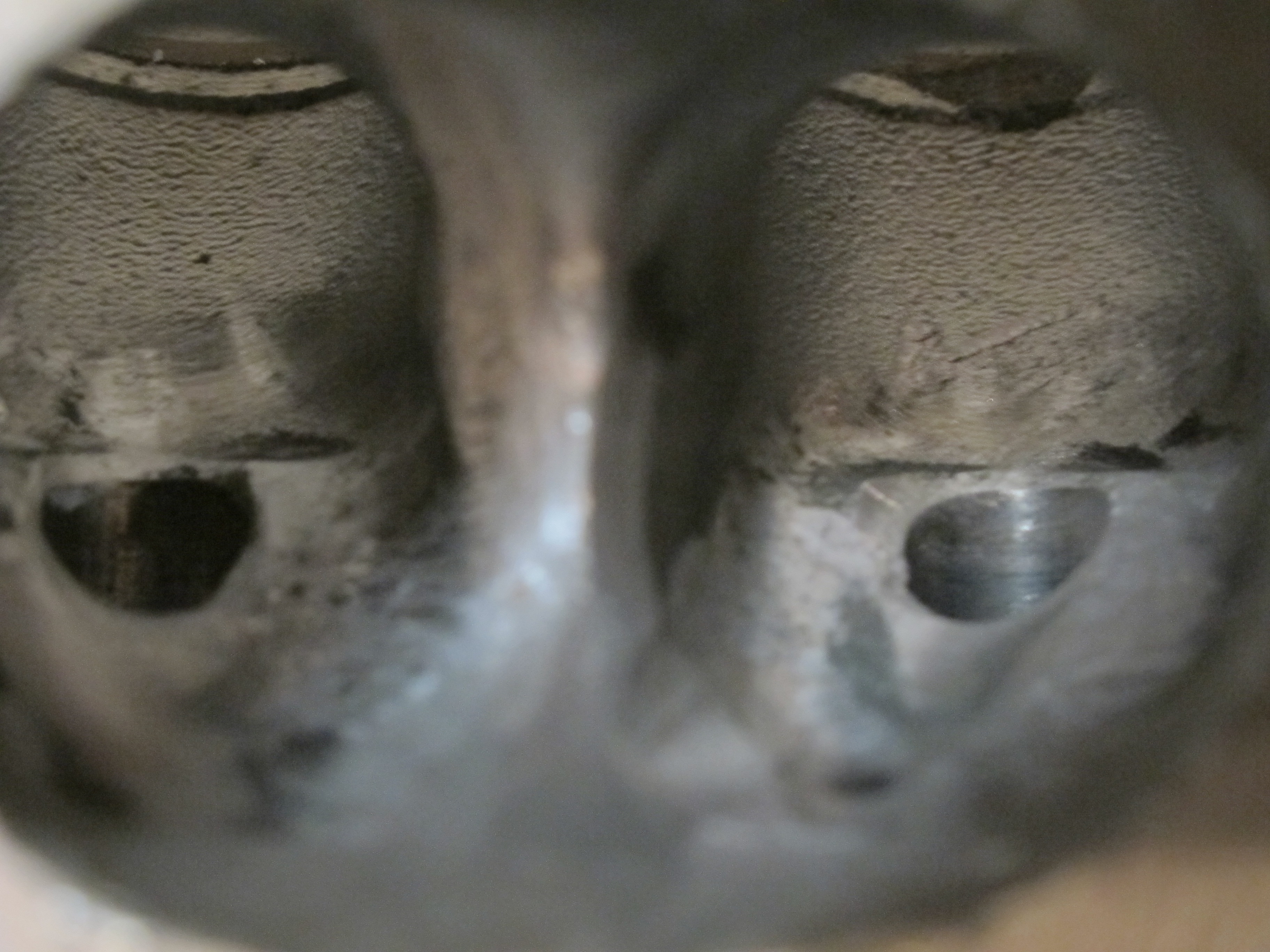
Here is the un-modified stock exhaust port. You can see there is a lot of work that is needed to be performed.

The amount of casting flash near the valves is surprising! The protrusion around the valve guides are generically marked for removal.

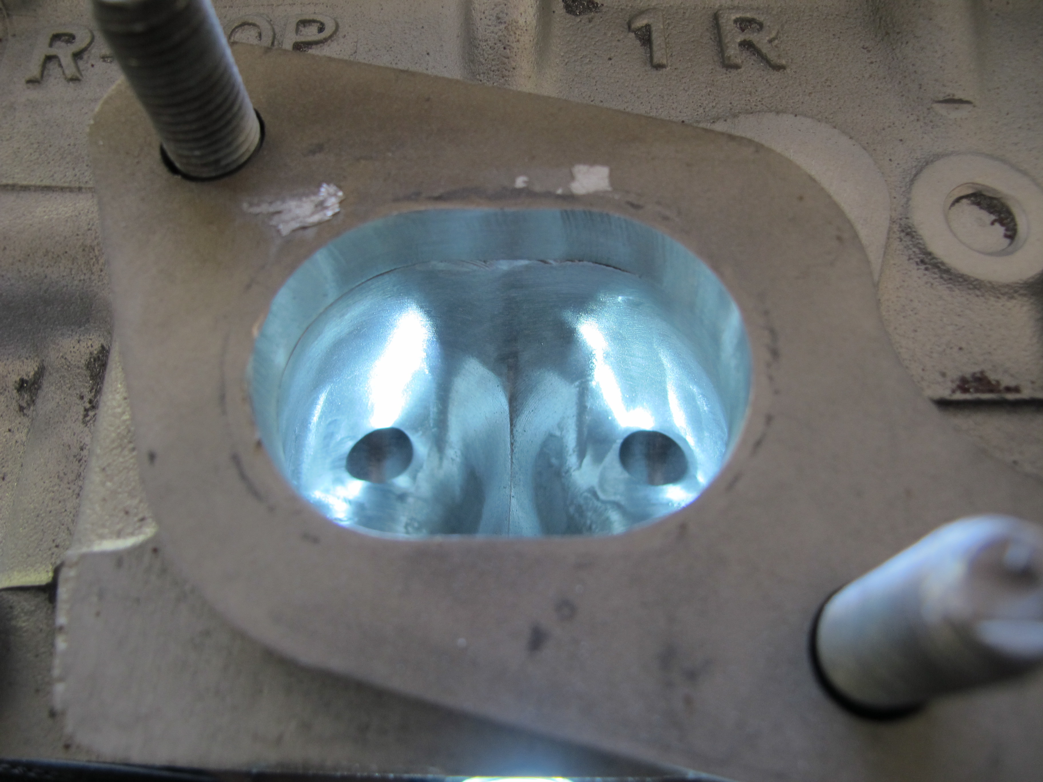
The basic shape has been started here, leaving only the valve guides to enter the port later on down the line when assembled.
Further smoothing the the shape is being worked over here.

This is the custom exhaust manifold flange hung on the head studs. I drafted 9 revised versions of this design in CAD before being totally satisfied with the outcome.

All lines are smoothed out for maximum flow.
The final surface treatment is fully blended to the port of the flange.
These heads will flow the exhaust gasses into the equal length manifolds & then into the Borg Warner EFR turbos rather well. Stay tuned for the next installment to see the turbo system go from dream to reality.
